Formula Racing Uprights
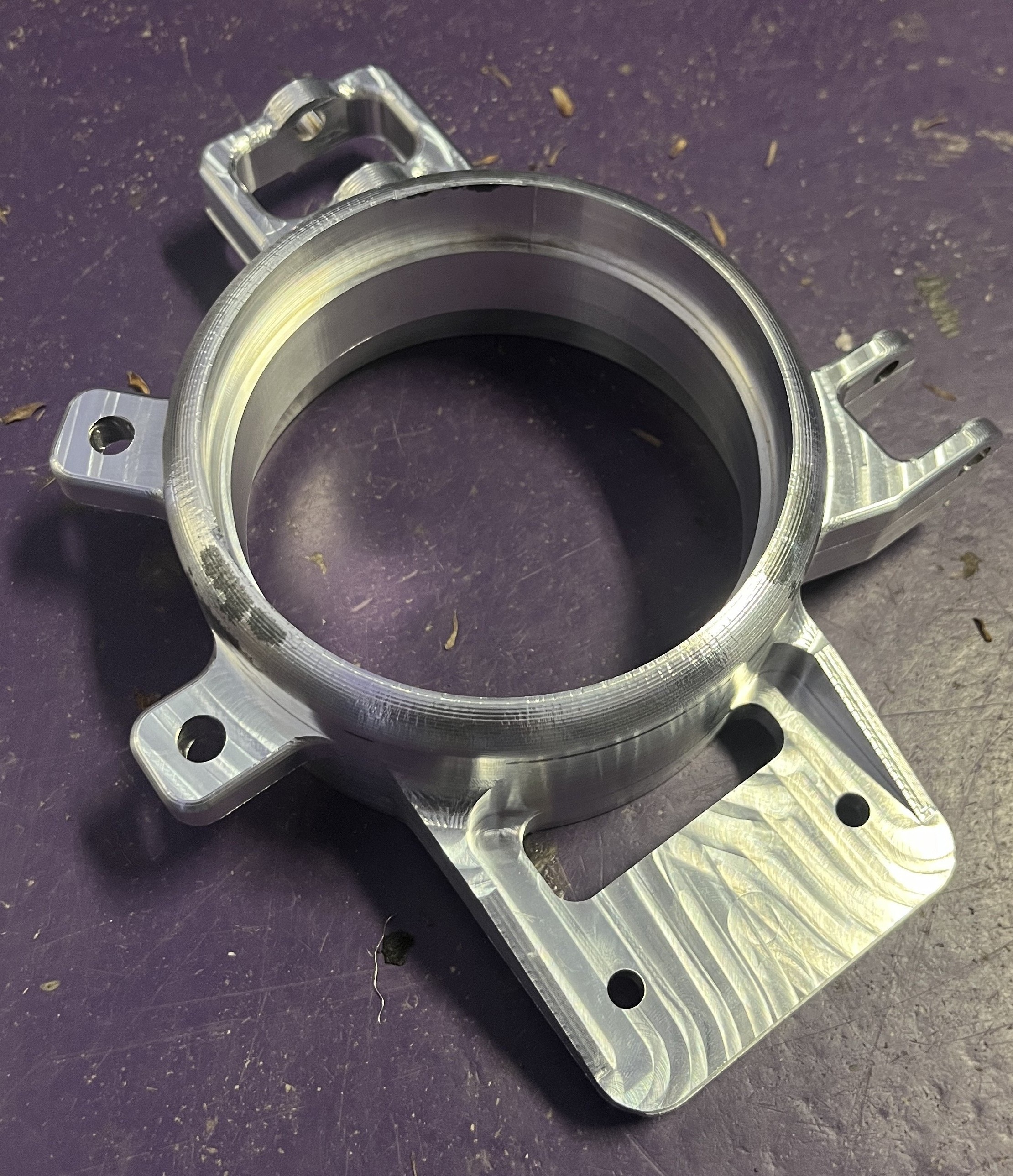
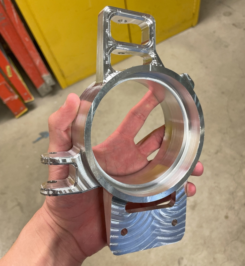
The uprights are a crucial part of any Formula SAE car. They link the suspension, wheel hub, and braking system, playing a vital role in ensuring optimal handling and stability. My goal when designing the uprights for the 2024 Northwestern Formula SAE car was to optimize strength and minimize weight, creating a part that both maximizes performance and keeps our driver safe.
I was responsible for the design, fabrication, and integration of the uprights into the car’s suspension. I used SOLIDWORKS CAD and FEA, Fusion 360 CAM and finally I CNC manufactured the parts on a 3-axis mill. Entering the project with limited experience in CAM and CNC manufacturing was challenging—I had to quickly master the CAM software and learn the ins and outs of operating a Haas mill, all while meeting a tight deadline to deliver a rolling chassis for the team. In the end, this became my favorite project yet. I learned that the best way to develop technical skills is through hands-on experience and that putting in extra hours is always worthwhile to achieve the team’s goals.
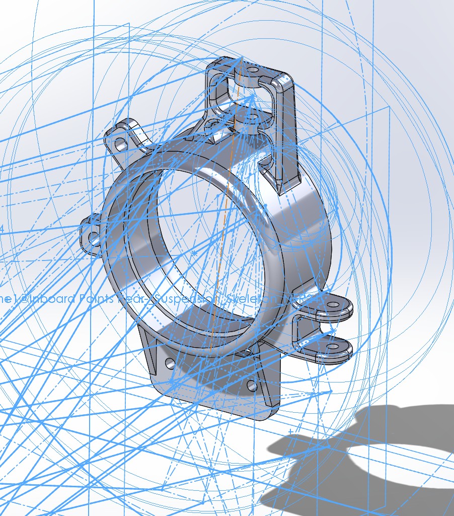
To create the CAD model of the Uprights, the entire suspension geometry was taken into careful consideration. An overlap of just a tenth of an inch with any other suspension component could have disastrous consequences for the car and driver. To avoid any mishaps, I used 3D sketched points referenced to the suspension skeleton to provide optimal spacing and clearance. The image to the left shows the upright in relation to the wheels, tie rod axes, wishbone axes, and axel.
Key components attached to the upright include upper and lower wishbones, a tie rod, brake calipers, and bearings for the wheel hubs. Maintaining precise tolerances was essential to ensure a proper press-fit for the bearings while allowing the wishbones and tie rod to rotate freely on multiple axes.
Next, various load cases were simulated on the upright using SOLIDWORKS FEA. After calculating forces in MATLAB, four load cases were tested—outside cornering, inside cornering, braking, and acceleration. Each of these cases was tested based on different fixtures of components. The testing showed that the upright didn’t come within 2 factors of safety for any load case.
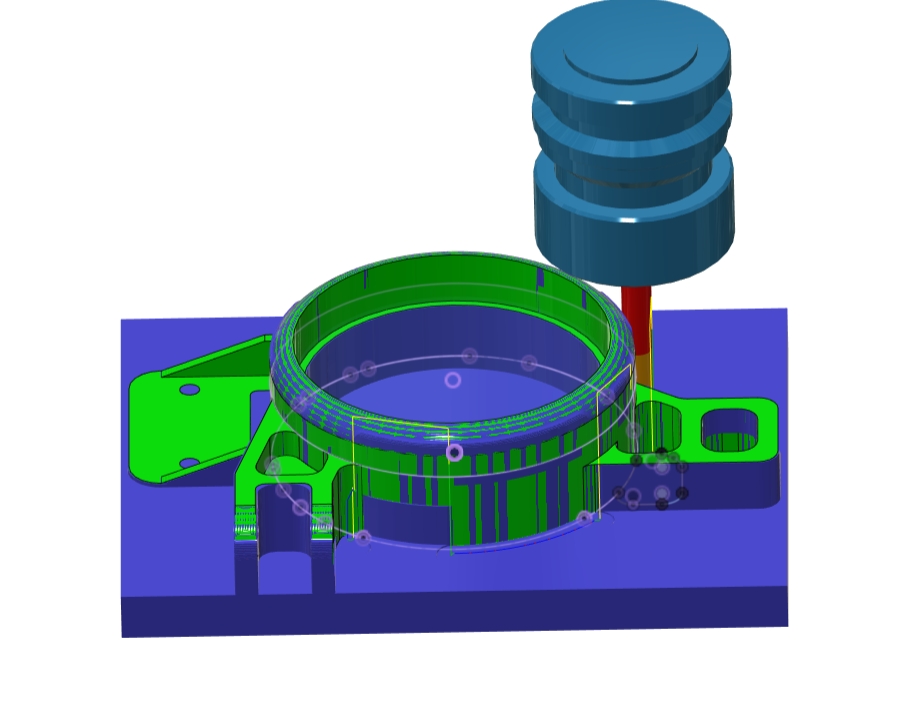
To bridge the gap between CAD and physical machining, Autodesk FUSION 360 was used to CAM program the upright. This process turned the SOLIDWORKS model into precise machining instructions for the CNC mill to run. During this process I had to learn the importance of tool selection, feeds and speeds, and the orientation of the part. By the time I finished a working CAM file, I had gained a comprehensive understanding of CAM processes.
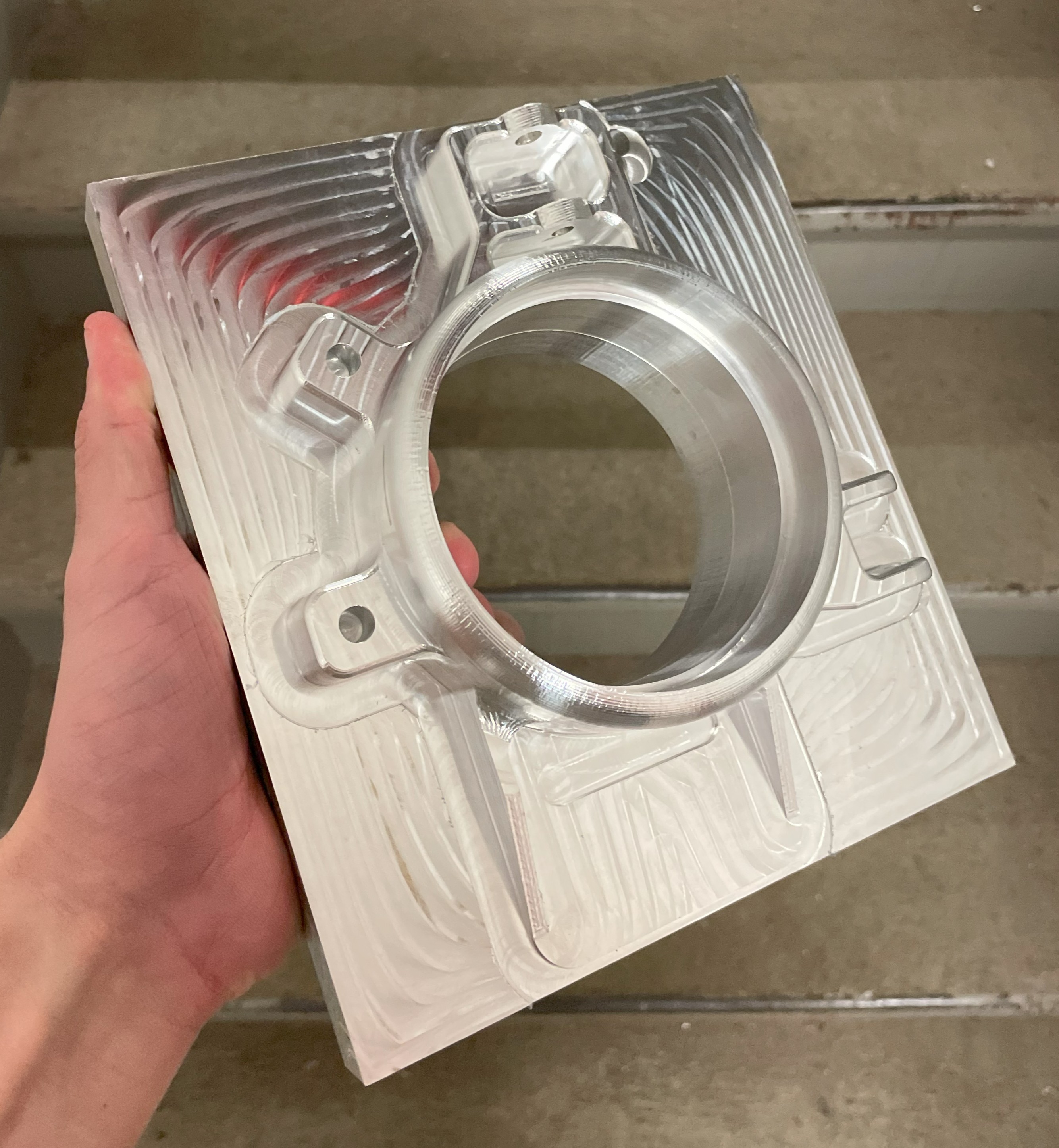
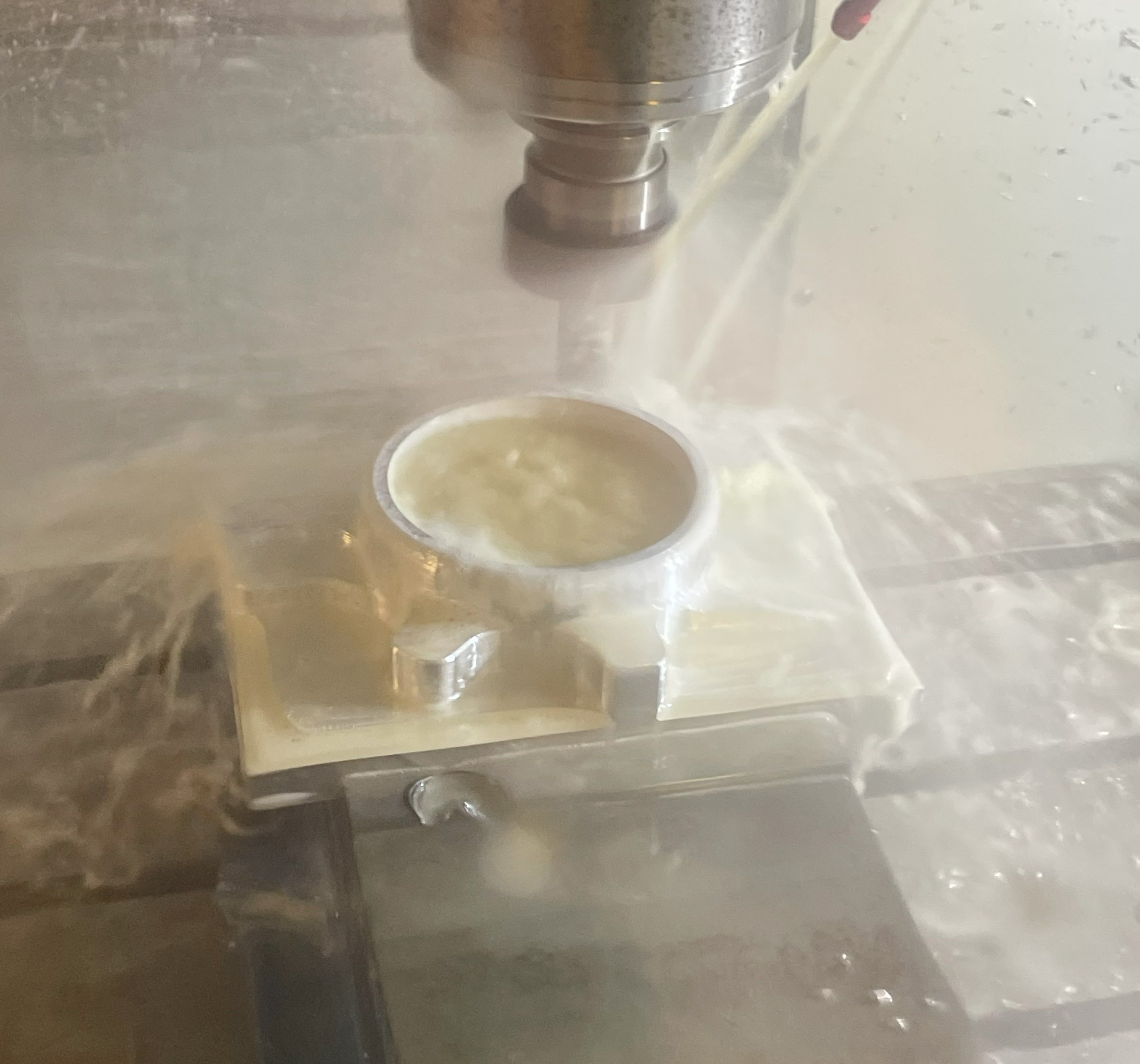
Finally, the part was manufactured out of a block of 70-75 aluminum using a 3-axis Haas mini mill. It took two setup cases to manufacture the entire upright, the second being much more complex than the first. For the first case, a traditional edge finder was used to find the zero point on a corner of the stock. To find the zero for the second setup, a spindle-mounted centering dial indicator was used on the center hole in the part.
After around 6 hours of machining each upright, all that was left to be done was to press fit the bearings in for the wheel hubs and to bolt the upright to all of the components. Once mounted on the NFR 24 car, the upright stayed undeformed and made no unwanted contact with any suspension components.
